Page 5 of 18
Re: F-35 Joint Strike Fighter
Posted: 11 Mar 2013, 16:44
by fishlips
Still aways to go with some cutting out of parts, some more smoothing and then texture mapping but it's getting there thanks to Kev's help with the nozzle and animations. The A & C model will hopefully go smooth.
These AI will probably be a WIP as the real F-35's change parts for others, along with better detailed blueprints.
JSF.jpg
Re: F-35 Joint Strike Fighter
Posted: 11 Mar 2013, 17:38
by MIKE JG
Looking good boys.
Make sure you back up the source files!!!!
Re: F-35 Joint Strike Fighter
Posted: 11 Mar 2013, 18:52
by DaleRFU
That looks sweet

Re: F-35 Joint Strike Fighter
Posted: 11 Mar 2013, 21:20
by fishlips
Make sure you back up the source files!!!!
Something that I'm often guilty of not doing regular. All updated onto my external hard drive!

Re: F-35 Joint Strike Fighter
Posted: 13 Mar 2013, 06:02
by fishlips
Kev,
When your finished with the texture mapping can you please email it to me and I'll start on the fuselage, no rush.

Re: F-35 Joint Strike Fighter
Posted: 13 Mar 2013, 08:19
by Weescotty
Funny you should say that.....
nozfin2.jpg
Re: F-35 Joint Strike Fighter
Posted: 13 Mar 2013, 08:22
by fishlips
Re: F-35 Joint Strike Fighter
Posted: 13 Mar 2013, 08:40
by fishlips
Kev, that look's sweet when fitted into the fuselage. Is this the final version or did you still have the animated feathers in mind ???
Thanks for your efforts on this project, you've been a vital part of bringing the aircraft forward to completion.
Mark
Re: F-35 Joint Strike Fighter
Posted: 13 Mar 2013, 09:17
by miljan
Excellent work both of you

Re: F-35 Joint Strike Fighter
Posted: 13 Mar 2013, 09:23
by Firebird
I have to say that for a troublesome feature you guys have overcome it remarkably well.
Re: F-35 Joint Strike Fighter
Posted: 13 Mar 2013, 12:19
by mikewmac
This is what can happen when two talented AI modelers collaborate closely.
Great work guys!
Mike M.
Re: F-35 Joint Strike Fighter
Posted: 13 Mar 2013, 12:30
by Weescotty
fishlips wrote:Kev, that look's sweet when fitted into the fuselage. Is this the final version or did you still have the animated feathers in mind ???
Thanks for your efforts on this project, you've been a vital part of bringing the aircraft forward to completion.
Mark
Still got animated feathers in mind.
Not 100% happy with the current animation.
Did some more digging.....
One site claims the cuts are at 45 degrees.
Plan is - create a disc then tilt it to 45 degrees, that way I can be sure it's a circle.
Create another disc that's vertical then manually create the polys between them.
Copy then mirror that part in the z-axis.
Finally create the polys between the two parts to get the middle section.
Then split into 3 and do the animation. Using this method only requires a 90 turn to make it point down.
Going to use this image to get the length right, I think the current one is a little long. Will do it as a ratio to the 'height' in the image.
http://sitelife.aviationweek.com/ver1.0 ... 2.Full.jpg
Re: F-35 Joint Strike Fighter
Posted: 13 Mar 2013, 12:52
by fishlips
Wow, Kev not sure what to say, you've done such a wonderful job... thank you.
PS: Kev, Please don't rush on my behalf, I'm still weeks away from a main model flight test. I also have a family trip to New Zealand coming up soon which will puts the brakes on. I'm trying to finish all the other general internal animated parts and then texture map the airframe before cutting the already designed hatch and flaps out prior to my departure but RL is also getting in the way. I think the F-35B is coming along nicely. I'll have to go back to design school again before starting on the other two variants which are somewhat different is design in several ways.
She'll be right!
Re: F-35 Joint Strike Fighter
Posted: 14 Mar 2013, 00:41
by Weescotty
fishlips wrote:Wow, Kev not sure what to say, you've done such a wonderful job... thank you.
PS: Kev, Please don't rush on my behalf, I'm still weeks away from a main model flight test. I also have a family trip to New Zealand coming up soon which will puts the brakes on. I'm trying to finish all the other general inturnal animated parts and then texture map the airframe before cutting the already designed hatch and flaps out prior to my departure but RL is also getting in the way. I think the F-35B is coming along nicely. I'll have to go back to disign school again before starting on the other two varants which are somewhat different is design in several ways.
She'll be right!
Email me the 3 views you are using and I will do a texture layout for the main parts.
Re: F-35 Joint Strike Fighter
Posted: 14 Mar 2013, 04:09
by fishlips
Kev,
The 3 views are a mix of drawing and photos that I've had to use. The 3D drawings were not good enough alone to provide the shape as they lacked detail in some areas.
I intend to use photo overlay where posible to acheive correct position of non-made parts. As I mentioned, this is WIP in the absence of blueprints.
Your very welcome to take a look if you please.
Re: F-35 Joint Strike Fighter
Posted: 15 Mar 2013, 01:23
by Weescotty
Just to bring everyone up to date -
After some more digging around looking for stuff on the nozzle......
The angled 'cuts' are perfect circles.
That being the case it means the rest of the casings are actually oval in shape, not round.
One site suggests at 45 degrees, but I think they are actually 22.5 degrees.
So I am going for nozzle Mk II -
a) Start off with a disk and scale it so that when it is tilted it is the correct vertical height.
b) Add another disk and scale it to the apparent (tilted) height of the original disk.
c) If you then look end on at the disks the second disk will appear narrower.
d) Scale the second disk to the width of the tilted disk, this results in an oval (just like the real thing).
e) Join the second to the first to maintain the tilted axis on the face.
f) Manually create the polys between them.
g) Copy then flip new part on the z-axis, and move to the correct position.
h) Copy both parts.
i) Join both the new parts.
j) Delete un-needed points then add the polys between the two angled surfaces to form the middle section.
If done right all the axis are in the right place at the correct angles.
a-->j works.
Animation I am toying with.
At the moment it is difficult because of FSDS's insistance of not using the part axis, but the global axis for rotation.
So I had an idea...(not tested yet)
If I create a heirachical poly by copy and pasting the mid section, then removing all points except 3 to make a poly.
Link this to the middle section - should result in all angles on the heirarchical part appearing as 0 (relative to the parent).
If I then link the rear exhaust part to the heirarchical poly they should also show 0.
Now if I rotate the whole part so the rear exhaust y-axis is lined up with the FSDS global y axis, I should only have to actually keyframe the z rotation.
Once done I can rotate the whole assembly back to its original position.
not sure if it will work but going to give it a bash....
Re: F-35 Joint Strike Fighter
Posted: 15 Mar 2013, 06:34
by fishlips
Sounds totally "Exhausting" work Kev!
Thanks you for your efforts.
Mark
Re: F-35 Joint Strike Fighter
Posted: 15 Mar 2013, 10:55
by gsnde
Sounds like 'Black Magic'. He lost me somewhere between a.) und b.)

Re: F-35 Joint Strike Fighter
Posted: 15 Mar 2013, 13:29
by DaleRFU
It blows my mind what you AI modelers go through to put aircraft in the skies

Re: F-35 Joint Strike Fighter
Posted: 15 Mar 2013, 14:14
by sr01
Kev and Mark , I’ll try and partially explain how this works , hoping that you can write the code .
I’ve labeled the casing # 1,2 and 3 in blue .The points of interest (PI) are labeled in green
Kev you are right in that the The angled 'cuts' are perfect circles.
Tthe rest of the casings are actually scalloped not oval in shape, or round so they’ll fit into the fuselage.
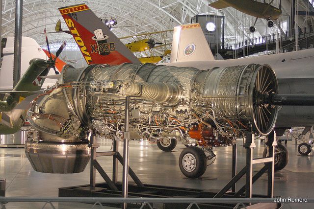
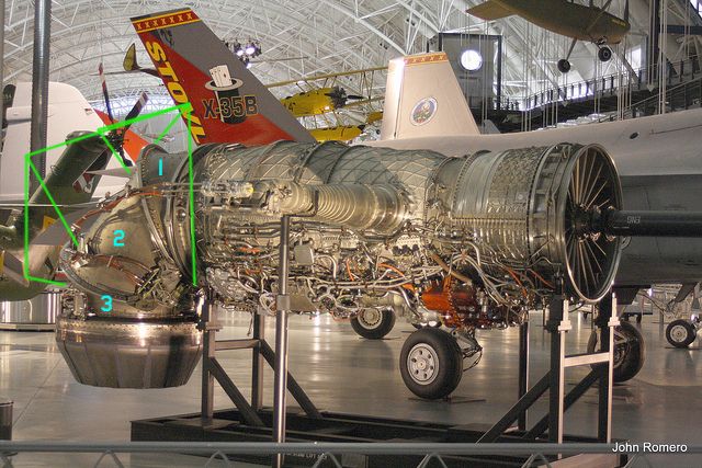
For the purposes of my attempt at explaining this , we are looking from stern to bow
all 3 casings have to stay along the centre line in the x axis .
When the exhaust nozzle move from horizontal to vertical , casing # 2 will rotate 90 degrees counterclockwise
As it’s doing that ,casings 1 and 3 will have to react by rotating at a slower speed clockwise to keep the x axis straight
Moving back up to the horizontal they’ll reverse the rotation .You can better visualize what I’m trying to explain here in this video
http://www.youtube.com/watch?v=28aMhIkvMHE
