Here goes.....
To start with, decide what basic shape you want your gear bays to have. Generally they'll be some sort of inside out box/rectangle structure.
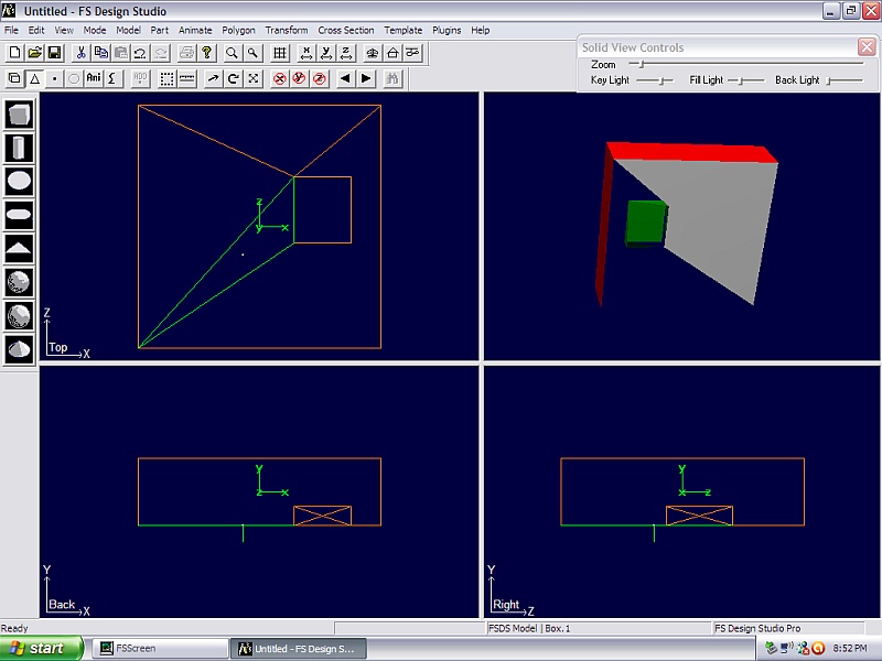
In the example below, the large red rectangle represents a fuselage and the small green box represents the gear bay.
One really good tip passed along to me by Jake Burrus (A-7, T-38, C-47, T-6, P-51, etc) was to try to model in halves. That way you only have to get one half of the shape correct as long as each side of the fuse is symmetrical. Especially when you are working with complex parts like the fuselage for this model, you have half the points/verticies to adjust and move around. Once you are happy with the half shape, you simply copy/paste and flip the newly copied fuselage part and then eventually join the two halves together and select snap to scale so that FSDS shades the whole part correctly.
So in this example we will pretend that we are working with one half of the fuselage section, left or right, doesn't really matter for this example.
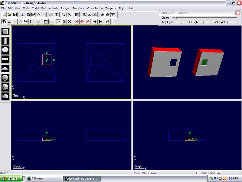
So once you have your fuselage part, insert you dummy gear bay part into your fuselage in the location that you want it to be.
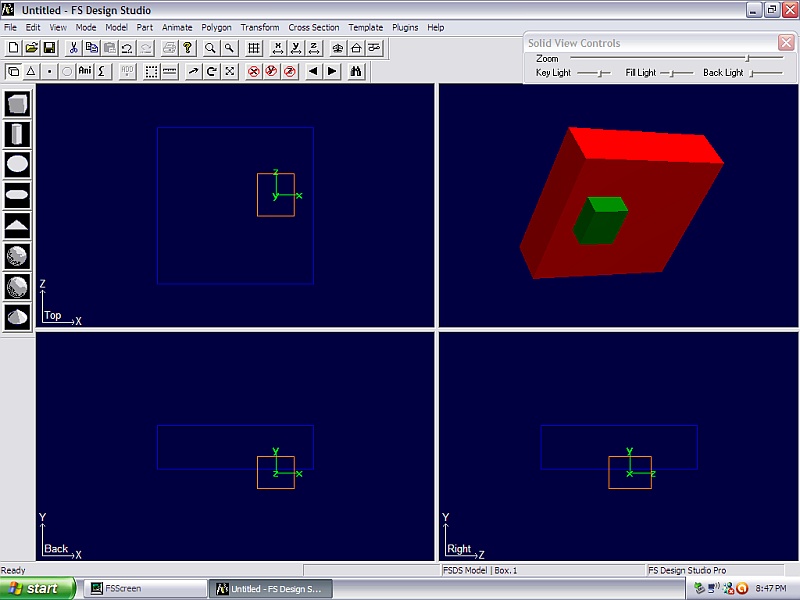
Notice these are still two separate parts at this point. Also I'm not concerned with the fact that the gear bay part sticks down below the bottom of my fuselage part, we'll fix that in a moment.
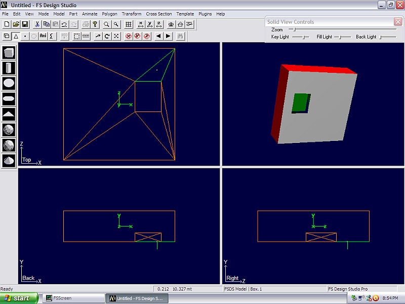
Now join these two parts to combine them into one single part. Once you've joined them together, go into polygon mode (F7) and delete any polygons that touch your gear bay part.
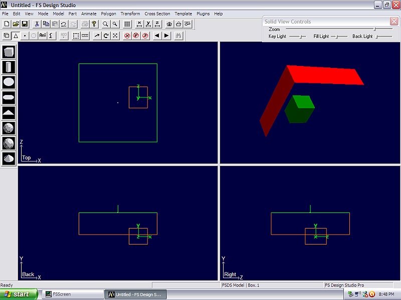
Since the red fuselage part is a simple box in this example, I only need to delete the bottom facing polygon which is what I've done in the picture above.
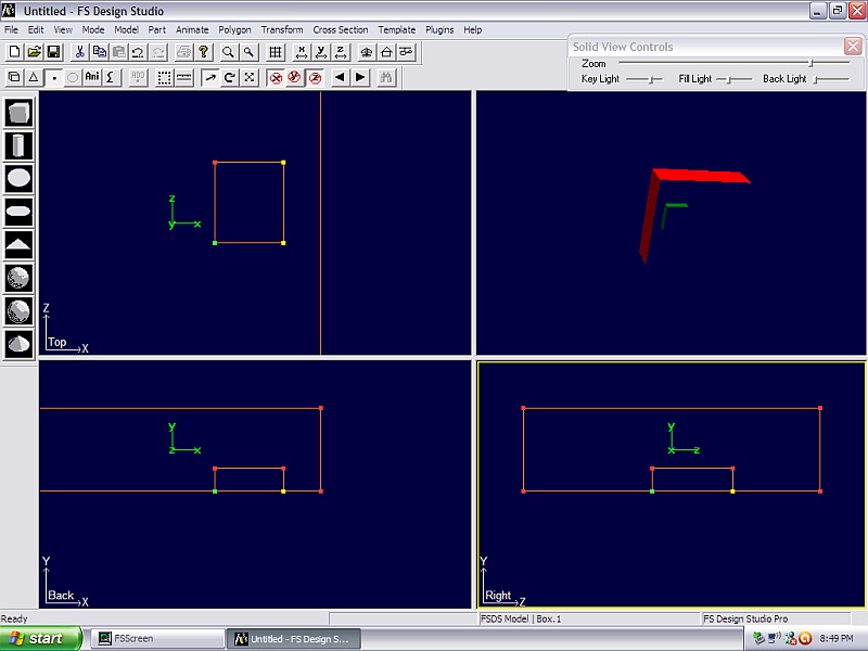
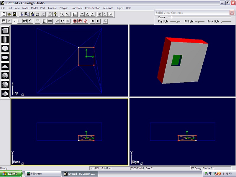
Now I can go into my single part and using point mode (F8) I can align the bottom set of points from my gear bay dummy part with the bottom of the fuselage part which is what I've done in this picture by simply using the move mode to move these bottom points up a little bit.
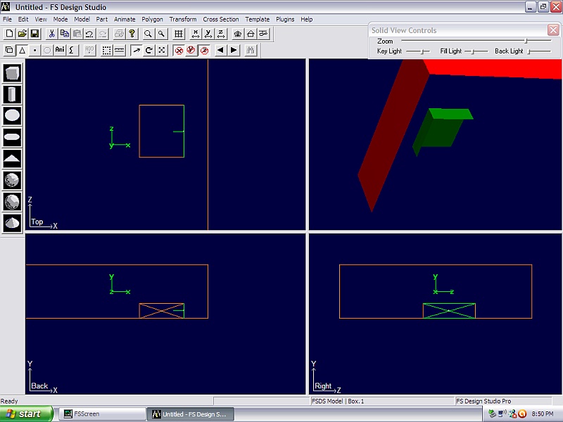
Now I can go back into poly mode (F7) and select the individual polygons that make up my gear bay, when I select each one, I press the "F" key to flip its orientation so that it forms an inside out box which is essentially what a gear bay is. So go to each of the polygons and flip them one by one until you get the insides of your gear bay. Don't worry about them making the x pattern like you see in this picture, we can fix that later.
Now we will start rebuilding the polygons that we deleted earlier. The difference is now we have our points/verticies for our gear bay in place so that we can build polys around that area and leave the gear bay there.
To rebuild the polys, we start selecting individual points/verticies by either scrolling to them or using the crosshairs (no mode selected) to click on each individual point and then pressing the space bar to highlight each one as we select it. Normally we need to select 3 points that are on the same plane so make sure you are selecting the bottom points/verticies since this part has points that overlap each other when viewed from above and from each side. Sometimes you can select more than 3 points and still get it to build you a polygon but that may or may not work.
So in my example I have started to build polygons, one at a time, around my gear bay, carefully selecting three points, highlighting each one as I select it, and then once I have 3 selected, pressing "Ctrl+P" to create a new polygon.
I continue this process until I completely rebuild the bottom of my fuselage part around my gear bay:

Now let's fix our gear bay polygons that are misbehaving. I can do that by using this same process of deleting the bad polys and then rebuilding them one by one. Before I do that, I need to now separate my parts so that I'm back to having separate fuselage and gear bay. Easiest way to accomplish that is to copy the main part, then go into point mode and delete the points associated with the gear bay. Once you've deleted the gear bay portion, select paste to paste the whole part again. Now using point mode, delete the points associated with the fuselage section. This will now leave you with just the gear bay portion as a separate part. Make sure to center the axis of the gear bay part.
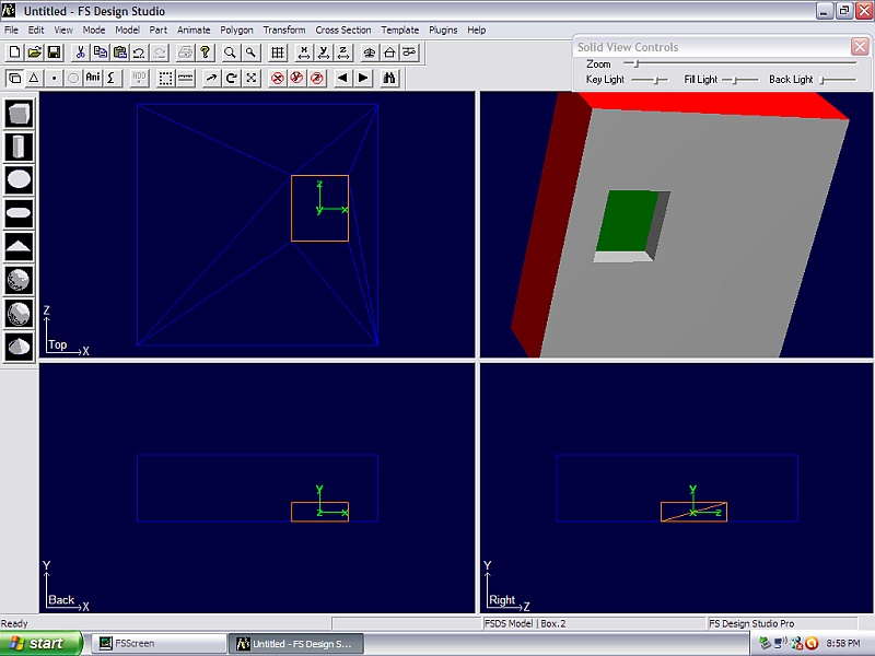
The end result is this picture where we have a completed bottom fuselage and a completed gear bay that are now separate parts that can be textured separately when the time comes. Note I still need to normalize the polygons of the gear bay.
Which I've now done in this image:
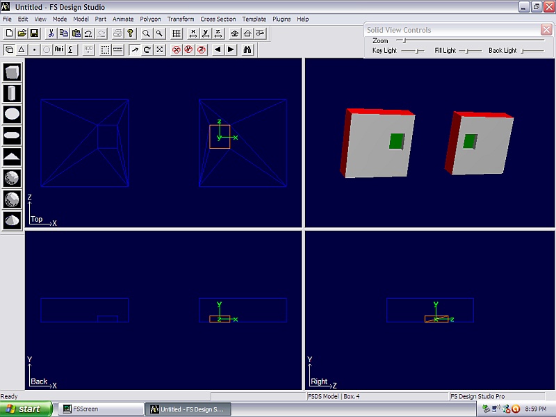
Now here's where modeling in halves really pays off. I can simply select my fuse half, copy it, paste it, select "Transform" and "Flip X". Then go into the parts properties menu and delete the negative sign in front of this part's X position. Doing so gives me the exact same part, mirrored and placed exactly on the other side of the Z axis as you see in this picture:
I need to repeat this copy/paste/flip/reposition technique with my gear bay part, which results in this:
I now have 4 separate parts, two fuselage halves and two gear bay parts. The beauty of this is that I know that each gear bay is identical to the other one, both are symmetrical which is normal for most models. I also know that I don't have any gaps in my 3D model.
Try this simple example first, then adapt these techniques to your fuselage part.
If you can't split your fuselage part into equal halves, you can still use this method but you just have to be a bit more careful and it takes a bit more work.
Hope this helps.